A crystal radio is the distilled essence of a radio. It has very few parts, it needs no batteries or other power source, and it can be built in a short time out of things you can find around the house.
The reason a crystal radio does not need any batteries is the amazing capabilities of the human ear. The ear is extremely sensitive to very faint sounds. The crystal radio uses only the energy of the radio waves sent by radio transmitters. These radio transmitters send out enormous amounts of energy (tens of thousands of watts). However, because they are usually far away, and we have at most a few hundred feet of wire for an antenna, the amount of energy we receive with the crystal radio is measured in billionths of a watt. The human ear can detect sounds that are less than a millionth of even that.
We are going to launch right into this chapter by building a working radio using parts that we buy at stores like Radio Shack or through mail order. We will try to use common household objects when we can, but our emphasis will be to quickly put together a radio that works.
Later we will learn more about radios by looking at even simpler versions that might not work as well as our first radio, but can show the important radio concepts more easily, because they have fewer parts.
Then we will improve our radio, making it louder, making it receive more stations, and making it look real nice.
Lastly, we will build each part of the radio from scratch, using things we find around the house. This will take a lot longer than our first radio, but it can be done by replacing store-bought parts one at a time, so we always have a working radio.
Our first radio
For our first radio, we will need these parts:
- A sturdy plastic bottle.I have used the plastic bottle that hydrogen peroxide comes in, or the bottles that used to contain contact lens cleaner. They are about three inches in diameter, and 5 to 7 inches long. Shampoo bottles also work, but you will want to get the ones with thick walls, rather than the thin flimsy ones. This will make it easier to wind wire around them.
- About 50 feet of enamel coated magnet wire.Most common gauges (wire diameters) will work, but thicker wire is easier to work with, something like 22 gauge to 18 gauge. This can be bought at Radio Shack (part number 278-1345), or you can take apart an old transformer or electric motor that is no longer needed. You can also use vinyl coated wire such as Radio Shack part number 278-1217, which in some ways is easier to use than enamel coated wire (it is easier to remove the insulation).
- A Germanium diode.Most stores that sell electronic parts have these. They are called 1N34A diodes (Radio Shack part number 276-1123). These are better for our radio than the more common silicon diodes, which can be used but will not produce the volume that Germanium diodes will. We also carry it in our catalog.
- A telephone handset.You listen to this radio just like you listen to the phone. If you have an old telephone sitting around, or can find one at a garage sale, you are set. Or you can buy the handset cord (Radio Shack part number 279-316) and borrow the handset from your home phone (using it for the radio will not harm it).
- A set of alligator jumpers.Radio Shack part number 278-1156, or you can find them anywhere electronics parts are sold.
- About 50 to 100 feet of stranded insulated wire for an antenna.This is actually optional, since you can use a TV antenna or FM radio antenna by connecting our radio to one of the lead-in wires. But it's fun to throw your own wire up over a tree or on top of a house, and it makes the radio a little more portable.
Use a sharp object like a nail or an icepick to poke four holes in the side of the bottle. Two holes will be about a half an inch apart near the top of the bottle, and will be matched at the bottom of the bottle with two more just like them. These holes will hold the wire in place.

Thread the wire through the two holes at the top of the bottle, and pull about 8 inches of wire through the holes. If the holes are large and the wire is loose, it is OK to loop the wire through the holes again, making a little loop of wire that holds snuggly.

Now take the long end of the wire and start winding it neatly around the bottle. When you have wound five windings on the bottle, stop and make a little loop of wire that stands out from the bottle. Wrapping the wire around a nail or a pencil makes this easy.

Continue winding another five turns, and another little loop. Keep doing this until the bottle is completely wrapped in wire, and you have reached the second set of holes at the bottom of the bottle.

Cut the wire so that at least 8 inches remains, and thread this remaining wire through the two holes like we did at the top of the bottle. The bottle should now look like this:


Now we remove the insulation from the tips of the wire, and from the small loops we made every 5 turns (these loops are called 'taps'). If you are using enameled wire, you can use sandpaper to remove the insulation. You can also use a strong paint remover on a small cloth, although this can be messy and smelly. Don't remove the insulation from the bulk of the coil, just from the wire ends and the small loops. If you are using vinyl coated wire, the insulation comes off easily with a sharp knife.

Next we attach the Germanium diode to the wire at the bottom of the bottle. It is best to solder this connection, although you can also just twist the wires together and tape them, or you can use aligator jumpers (Radio Shack part number 278-1156) if you are really in a hurry.
Cut one end off of the handset cord to remove one of the modular telephone connectors. There will be four wires inside. If you are lucky, they will be color coded, and we will use the yellow and black wires. If you are not lucky, the wires will be all one color, or one will be red and the others will be white. To find the right wires, first strip off the insulation from the last half inch of each wire. Then take a battery such as a C, D, or AA cell, and touch the wires to the battery terminals (one wire to plus and another to minus) until you hear a clicking sound in the handset earphone. When you hear the click, the two wires touching the battery are the two that go to the earphone, and these are the ones we want.
The 'wires' in the handset cord are usually fragile copper foil wrapped around some plastic threads. This foil breaks easily, sometimes invisibly, while the plastic threads hold the parts together making it look like there is still a connection. I recommend carefully soldering the handset wires to some sturdier wire, then taping the connection so nothing pulls hard on the copper foil.
Attach one handset wire to the free end of the Germanium diode. Solder it if you can.
Attach the other wire to the wire from the top of the bottle. Soldering this connection is a good idea, but it is not necessary.
Now clip an alligator jumper to the antenna. Clip the other end to one of the taps on the coil.
Clip another alligator lead to the wire coming from the top of the bottle. This is our 'ground' wire, and should be connected to a cold water pipe or some other metal object or wire that has a good connection to the earth.

At this point, if all went well, you should be able to hear radio stations in the telephone handset. To select different stations, clip the alligator jumper to different taps on the coil. In some places, you will hear two or more stations at once. The longer the antenna is, the louder the signal will be. Also, the higher you can get the antenna the better.
Now that your radio works, you can make it look better and be sturdier by mounting it on a board or in a wooden box. Machine screws can be stuck into holes drilled in the wood to act at places to attach the wires instead of soldering them. A radio finished this way looks like the following photo. Note the nice little touch of using brass drawer pulls on the machine screws to hold the wire.

Building a radio in 10 minutes.
For our 10 minute radio, we will need these parts:
- A ferrite loop antenna coilIn our other crystal radios we wound the coil by hand. In this project we use a much smaller coil with a ferrite rod inside, from our catalog. The ferrite rod allows the coil to be smaller, and it can be moved in and out of the coil for coarse tuning.
- A variable capacitor (30 to 160 picofarads)We carry this in our catalog. You can also find them in old broken or discarded radios.
- A Germanium diode (1N34A)We carry this in our catalog.
- A piezoelectric earphoneAlso in our catalog.
- Two alligator jumper wiresWe use alligator jumper wires here for convenience. They are used to connect the ground and antenna wires to a good ground and a long wire antenna. We carry these in our catalog.
- About 50 to 100 feet of stranded insulated wire for an antenna.This is actually optional, since you can use a TV antenna or FM radio antenna by connecting our radio to one of the lead-in wires. But it's fun to throw your own wire up over a tree or on top of a house, and it makes the radio a little more portable.
- A block of wood or something similar for a base
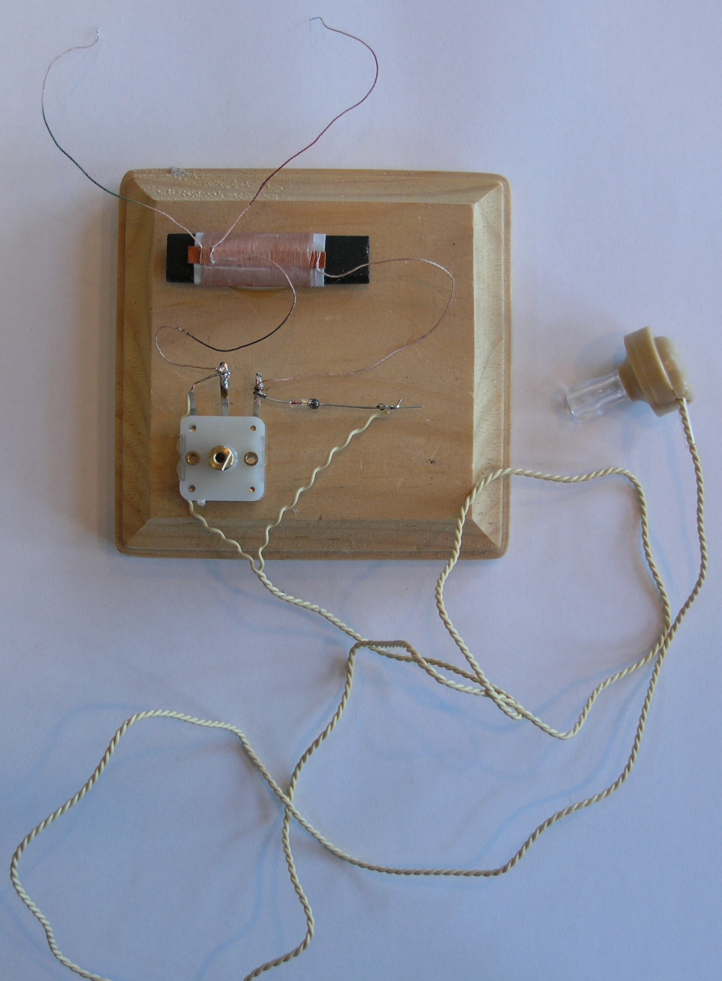
Click on photo for a larger picture
You can see from the photo how simple this radio is, and why it can be put together in a very short time.
The black painted wire from the ferrite loop is soldered to the center lead of the variable capacitor. The unpainted wire is soldered to the rightmost lead of the variable capacitor.
The germanium diode is soldered to the rightmost lead of the variable capacitor.
One of the piezoelectric earphone wires is soldered to the free end of the germanium diode. The other is soldered to the center lead of the variable capacitor.
The red painted wire of the coil is attached to the long wire antenna with an alligator clip lead.
The green painted wire of the coil is attached to a good ground (such as a cold water pipe) using another alligator clip lead.
That's it -- you're done!
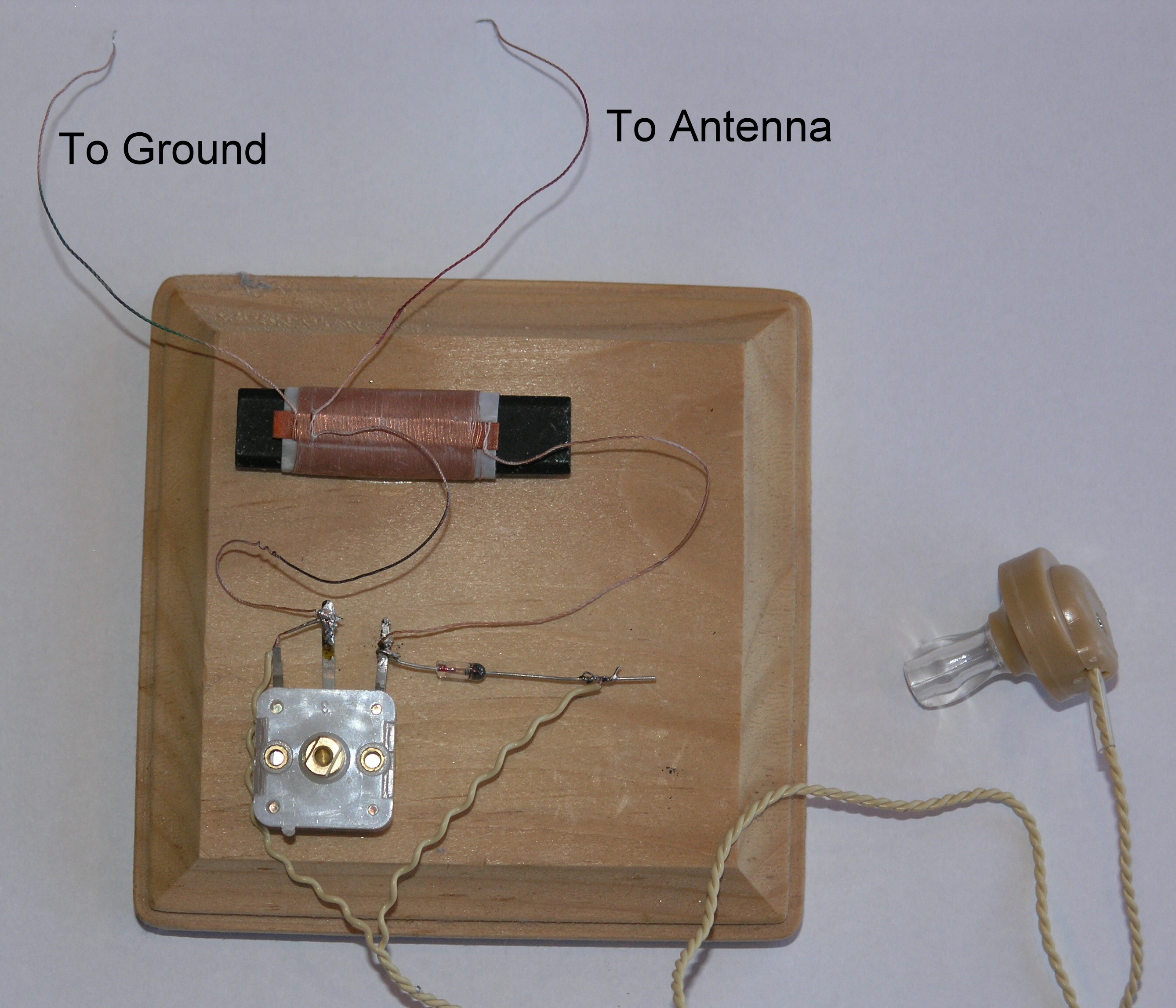
Click on photo for a larger picture

How does it work?
We will start the tuning with the variable capacitor set in the middle of its range, neither all the way clockwise, nor all the way counter clockwise.
With the earphone in your ear, slowly move the ferrite rod into the coil, listening for radio stations.
With a long antenna, you can tune several radio stations. In some areas, one or two stations will be so close or so powerful that they overwhelm all the others, and you will only hear those one or two stations.
How does the ferrite change the frequency?
The ferrite rod increases the inductance of the coil. In our other (hand-wound) coils, we increased the inductance by winding some more loops, or by using a "tapped" coil, and selecting a tap that was farther down the coil.
As the ferrite rod is inserted into the coil, more of the coil is affected by the ferrite, and so the inductance increases. Increasing the inductance moves the frequency lower. This allows us to hear stations "lower on the radio dial".
Ferrite is used because it is magnetic, like iron or steel, but it is not a conductor of electricity. If it were conductive, the coil would induce "eddy currents" in it, and some of the energy would be lost heating up the core. Because ferrite is not a conductor, we can use its magnetic properties to change the inductance of the coil, without losing volume.
If you have a long antenna, a good ground, and you are not too close to a strong station, the variable capacitor will help in fine tuning the stations.
There are actually two coils of wire wound around the ferrite rod. The large coil is connected to the variable capacitor. The small coil is connected to the antenna and ground.
This arrangement allows the radio to be more selective, so that strong stations don't drown out the weak ones. Really strong local stations will still overwhelm the more distant stations, however.
If you have no strong local stations, you can make the stations you receive sound louder by connecting the antenna and ground directly to the large coil. Connect the antenna to the center lead of the variable capacitor, and the ground to the rightmost lead of the variable capacitor. The stations will be louder, but they will most likely all be heard at once, since you radio will be less selective in tuning out adjacent stations.
Fonte: http://sci-toys.com/scitoys/scitoys/radio/radio.html


Uma outra opção: Uma das coisas mais divertidas de se fazer quando criança é montar circuitos eletrônicos (ok ok tudo bem que nem todas as crianças gostam…)
Uma dos primeiros circuitos que montei quando criança foi um radio galena muito semelhante ao mostrado no circuito abaixo, foi uma grande alegria ver que algo tão simples funcionava tão bem 
Acima temos um circuito de Radio Galena, que não faz uso de um capacitor variavel para ajustar a frequência que desejamos sintonizar, para simplificar a montagem o circuito utiliza o conceito de indutância variavel o que é obtido variando-se a derivação da bobina. Como podem ver este rádio não usa nenhum tipo de alimentação elétrica.
Se você quiser montar o radio acima com seu filho, você vai precisar de:
Se você quiser montar o radio acima com seu filho, você vai precisar de:
- 20 metros de fio de cobre # 24, para construção da bobina;
- 20 metros de fio de cobre # 22 para construção do fio terra e da antena;
- 1 tubo de PVC, com 10 a 12 cm de comprimento e diâmetro entre 2,5 e 3,0 cm;
- 1 capacitor cerâmico de 78 pF;
- 1 diodo de germânio para RF, como por exemplo o 1N34;
- 1 fone de ouvido de alta impedância (cristal), fones atuais de 8 ohms nao servem;
A montagem é muito simples  , e se vc fizer com carinho fica parecido com o mostrado abaixo:
, e se vc fizer com carinho fica parecido com o mostrado abaixo:
Nenhum comentário:
Postar um comentário